Detectors for Heavy
Fragments : Design
[1]
Overview
Position
detectors
Beam is momentum-tagged by measureing the
position at the momentum dispersive focal plane (F5).¹@ Beam phase space is measured by a set of position detectors
befort the target.¹@ From the required
momentum resolution and the bending power of the magnet, tracking detectors are
designed to have an angular resolution of about ![]() , assuming
that the beam positions are measured by extrapolating the beam trajectory, and
that positions and angles are measured downstream of the magnet.¹@ In addition, another chamber is installed
between the target and the magnet to measure the scatteering angle.¹@ In addition, This requires a low-mass
chamber, much less than
, assuming
that the beam positions are measured by extrapolating the beam trajectory, and
that positions and angles are measured downstream of the magnet.¹@ In addition, another chamber is installed
between the target and the magnet to measure the scatteering angle.¹@ In addition, This requires a low-mass
chamber, much less than ![]() , with a good
position resolution.¹@
, with a good
position resolution.¹@
Detectors
for Particle Identification
¹@ Particle identification
of heavy fragments requires velocity measurement or total-energy measurement in
addition to the rigidity and the charge measurement.¹@ In order to have 5s separation (![]() ) at A=100,
velocity resolution of
) at A=100,
velocity resolution of ![]() ¹@or total energy resolution of
¹@or total energy resolution of ![]() ¹@is necessary.¹@ When the TOF method is used for velocity measurement, necessary
time resolution is
¹@is necessary.¹@ When the TOF method is used for velocity measurement, necessary
time resolution is ![]() ¹@for 10 meters of flight path.¹@ Considering the necessity of a thin start
detector for TOF, this method seems to be marginal.
¹@for 10 meters of flight path.¹@ Considering the necessity of a thin start
detector for TOF, this method seems to be marginal.
¹@We have considered two techniques for
velocity and total-energy measurements: a Cherenkov detector operated at the
total internal reflection (TIRC) for velocity measurement and pure CsI detector
for total-energy measurement.
Design
policy
¹@¹@¹@ Since all the detailed design of these
detectors (i.e. all the contracts) had to be made¹@ in FY2008 due to the nature of the construction budget, design of
these detectors are , more or less, conventional.
Detector
Summary
¹@¹@ There are four kinds of detector groups for
heavy ion measurements.
*
Position measurement
* Beam Proportional Chamber
(BPC):¹@¹@¹@¹@¹@¹@¹@¹@¹@¹@¹@¹@¹@¹@¹@¹@ beam rigidity tagging at F5
* Beam Drift Chamber
1, 2 (BDC1,BDC2) :¹@¹@¹@¹@¹@¹@¹@¹@¹@¹@¹@ beam
phase space
* Forward Drift Chamber
1 (FDC1)
:¹@¹@¹@¹@¹@¹@¹@¹@¹@¹@¹@¹@¹@¹@¹@¹@¹@ scattering angle of
fragments
* Forward Drift Chamber
2 (FDC2)
:¹@¹@¹@¹@¹@¹@¹@¹@¹@¹@¹@¹@¹@¹@¹@¹@¹@ rigidity analysis¹@ for fragments
* Proton Drift Chamber
1,2 (PDC1,2) :¹@¹@¹@¹@¹@¹@¹@¹@¹@¹@¹@¹@¹@¹@¹@¹@¹@¹@¹@¹@¹@¹@¹@ momentum
analysis for protons
*
Charge measurement
* Ion Chamber for Beam
(ICB)
:¹@¹@¹@¹@¹@¹@¹@¹@¹@¹@¹@¹@¹@¹@¹@¹@¹@¹@¹@¹@ beam charge
* Ion Chamber for Fragments
(ICF)
:¹@¹@¹@¹@¹@¹@¹@¹@¹@¹@¹@¹@¹@¹@¹@¹@ fragment charge
*
Velocity (& charge) measurement
* Hodoscope for Fragment ( HODF) :¹@¹@¹@¹@¹@¹@¹@¹@¹@¹@¹@¹@¹@¹@¹@¹@ velocity & charge for
fragments
* Hodoscope for Protons (HODP) :¹@¹@¹@¹@¹@¹@¹@¹@¹@¹@¹@¹@¹@¹@¹@¹@¹@¹@ velocity & charge for
protons
* Total Internal Reflection
Cherenkov (TIRC) :¹@¹@¹@¹@¹@¹@¹@¹@¹@ velocity
for fragments
*
Total energy measurement
* Total Energy Detector
(TED)
:¹@¹@¹@¹@¹@¹@¹@¹@¹@¹@¹@¹@¹@¹@¹@¹@¹@¹@¹@¹@ total energy
*
Readout electronics for position detectors
¹@ As a readout circuits of position detectors,
anode signals are converted into LVDS logic signals using Amp-Shaper-Discriminator
boards (ASD, 16ch/board, gnd, GNA210) mounted directly on the detectors.¹@ ASD Power Supply modules are used to supply
¹}3V, threshold voltage, and test pulses : one ASD PS handles 10 ASD boards.¹@ Logic signals are further processed by multihit
TDC¹fs (AMSC, 64ch AMT-VME TDC module) with 0.8 nsec/ch precision.
*
Gas mixture for position detectors
¹@ When detectors are operated at 1 atm,
He+60%CH4 is used.¹@ This
mixture comes from the compromise among multiple scattering, position resolution
and running cost.¹@ At low pressure, BPC,
BDC, and FDC1 are operated using pure i-C4H10.
[2]¹@ Beam Proportional Chamber
(BPC)
*
Design
¹@¹@¹@¹@ BPC is used to tag the rigidity of
secondary beams at the momentum dispersive focal plane F5 by measuring the horizontal
position.¹@ It is a 4mm-spacing multiwire
proportional chamber with 2 anode planes.¹@
It is housed in detector box, which is placed in the F5 vacuum chamber.¹@ Since the momentum dispersion at F5 is
~33mm/%, 4mm-spacing provides momentum resolution of less than 0.1% (rms).
BPC
is shown in Fig. 1 and summarized in the table.
¹@ Amp-shaper-discriminators (ASD) are mounted
directly on the detector box in the F5 vacuum chamber.¹@ LVDS signals are timed , through the vacuum
feed through, by TDC¹fs.¹@ Isobutane gas
is used at about 20 torr for Kr, and about 200 torr for protons.
|
Anode |
20É mÉ” Au-W/Re |
|
Anode
spacing |
2mm
(2 wires are or-ed¹@ for readout) |
|
Anode
– cathode gap |
5mm
(5mm-thick G10) |
|
Cathode,
window |
12É m-thick Al-Mylar |
|
Effective
area |
240mm
(H) x 150mm (V) |
|
Anode
configuration |
x1
- x2 |
|
#readout
channels |
64
anodes /plane x 2 planes = 128anodes |
|
Window
of detector box |
80É m-thick Kapton x2 |
|
Operation
gas |
i-C4H10
at 20 to 200 torr |
|
HV |
cathode |
|
Readout |
ASD
x8,¹@ ASD PS x1,¹@ TDC x2 |
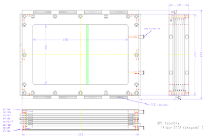
Fig. 1 : BPC assembly
¹@[3] Beam Drift Chambers
(BDC1, BDC2)
*
Design
¹@ Two sets of BDC¹fs are used to measure the
phase space of the incident secondary beams on the reaction target.¹@¹@ It is a Walenta-type drift chamber with
2.5mm drift distance for high beam rates.¹@¹@
BDC is shown in Fig. 2, and summarized in the table.
|
Anode
wire |
16É mÉ” Au-W/Re |
|
Potential
wire |
80É mÉ” Au-Al |
|
anode
– potential (drift) distance |
2.5mm |
|
anode
– cathode gap |
2.5mm
(combination of 2.4mm & 2.6mm-thick G10) |
|
cathode |
8É m-thick Al-Kapton, x 9 |
|
gas
window |
4É m-thick Aramid, x2 |
|
effective
area |
80mm
x 80mm |
|
anode
configuration |
xx¹fyy¹fxx¹fyy¹f |
|
#anode
/ plane x #planes |
16
wires/plane x 8 planes = 128 wires/detector |
|
Operation
gas |
He+60%CH4
at 1 atm, i-C4H10 below 200 torr |
|
HV |
cathode,
potential |
|
Readout
/ 2sets |
ASD
x16,¹@ ASD PS x2,¹@ TDC x4 |
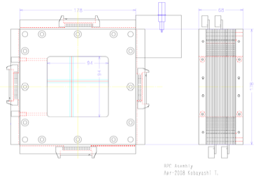
Fig. 2 : BDC assembly
¹@[4]¹@ Forward
Drift Chamber 1 (FDC1)
*
Design
¹@ FDC1 is placed between the target and
SAMURAL magnet in order to measure the emission angle of the projectile
fragments.¹@ It also has wide opening in
order not to interfere with projectile-rapidity neutrons at zero degrees.¹@¹@ It is a Walenta-type drift chamber with 5mm
drift distance in order to handle relatively high beam intensity right after
the target.
|
anode
wire |
20É mÉ” Au-W/Re |
|
potential
wire |
80É mÉ” Au-Al |
|
anode
– potential (drift) distance |
5mm |
|
anode
– cathode gap |
5mm
(5mm-thick G10) |
|
cathode |
8É m-thick Al-Kapton, x
15 |
|
gas
window |
8É m-thick Al-Kapton, x2 |
|
effective
area |
315mmÉ” |
|
open
area for neutrons |
620mm
x 340mm |
|
anode
configuration |
xx¹fuu¹fvv¹fxx¹fuu¹fvv¹fxx¹f,
(¹}30¹΄ for u/v) |
|
#anode
/ plane x #planes |
32
wires/plane x 14 planes = 448 wires |
|
operation
gas |
He+60%CH4
at 1 atm, i-C4H10 at low pressure |
|
HV |
cathode,
potential |
|
Readout |
ASD
x28,¹@ ASD PS x3,¹@ TDC x7 1 VME crate (with
BDC1,2) |
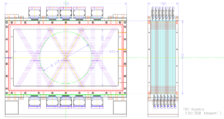
Fig. 3 : FDC1 assembly
¹@[5]¹@ Forward
Drift Chamber 2 (FDC2)
*
Design
¹@¹@ FDC2 is placed after SAMURAI magnet for rigidity
analysis of projectile fragments.¹@ The
cell structure is hexagonal with 10mm drift length.¹@ Two staggered planes named super layer, such as xx¹f, are
separated by 100mm pitch with shield planes in between.
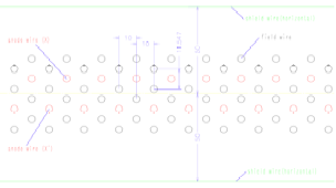
Fig 4 : FDC2 cell
structure
¹@¹@ Although it was originally planned to put
FDC2 in the detector box for low-pressure operation, FDC2 will be operated at 1
atom for the time being due to technical difficulties.
|
Anode
wire |
40É mÉ” Au-W/Re, 20mm pitch |
|
Field
& shield wire |
80É mÉ” Au-Al, 20mm pitch |
|
Cell
structure |
hexagonal,
10mm drift length |
|
Configuration |
s-xx¹f-s-uu¹f-s-vv¹f-s-xx¹f-s-uu¹f-s-vv¹f-s-xx¹f-s¹@ (¹}30¹΄for u/v) |
|
window |
2296mm
x 836mm |
|
#anode
wires (dummy) |
224(4)
anodes/super layer x 7 super layer = 1568 (28) anodes |
|
#field
/ shield wires |
4788
(field), 328 (shield) |
|
Operating
gas |
He+60%CH4
at 1 atm ( i-C4H10 below 100 torr) |
|
HV |
field
wires, shield wires |
|
Readout |
ASD
x98,¹@ ASD PS x11,¹@ TDC x25, 2 VME crates |
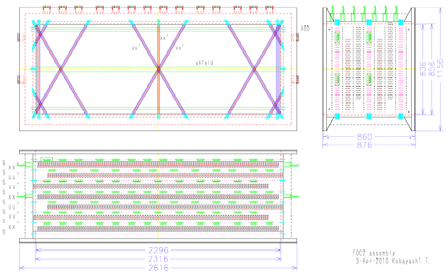
Fig. 5 : FDC2 Assembly
[6]¹@ Proton Drift Chamber 1,
2 (PDC1, PDC2)
*
Design
¹@ PDC1 and PDC2 are placed downstream of
SAMURAI magnet, and used to measure the momentum of projectile-rapidity
protons.¹@ Since counting rate is
expected to be low and in order to reduce number of planes, position
information is obtained using the cathode readout method.¹@ For the anode plane, Walenta-type drift
chamber, with 8mm drift length, is adopted in order to reduce the number of
anode wires.¹@ Three kinds of cathode
orientation are used to detect multi particles.
¹@ Parameters for the cathode readout are as
follows.
|
anode
wire |
30É mÉ” Au-W/Re, 16mm pitch
(8mm drift length) |
|
potential
wire |
80É mÉ” Au-Al, 16mm pitch |
|
anode
– cathode gap |
8mm |
|
cathode
wire |
80É mÉ” Au-Al, 3mm pitch |
|
cathode
strip width |
12mm
(4 cathode wires are or-ed for one strip) |
¹@¹@ Present design of PDC is as follows.¹@ Anode wires are or-ed and positive HV is
applied.¹@ Anode wires are not
readout.¹@ Slight negative HV is applied
to potential wires.¹@¹@ Cathode strips are
directly connected to the readout without decoupling capacitors.
¹@ Present design of the PDC is shown in Fig 6.
|
configuration |
cathode(U)-Anode(V)-cathode(X)-anode(U)-cathode(V) |
|
wire
angle |
X(0¹΄), U(+45¹΄), V(-45¹΄) |
|
Effective
area |
1700mm
x 800mm |
|
anode
wire (U,V) |
106
anodes/plane x 2cplanes = 212 anodes |
|
potential
wire (U,V) |
107
potentials/plane x 2 planes = 214 potentials |
|
cathode
wire (U,V,X) |
544
wires/plane,¹@ 136 cathode strips (4
wires are or-ed)/plane |
|
HV |
Anode(+),
potential(-) |
|
Operating
gas |
Ar+25%
i-C4H10 or Ar+50%C2H6 |
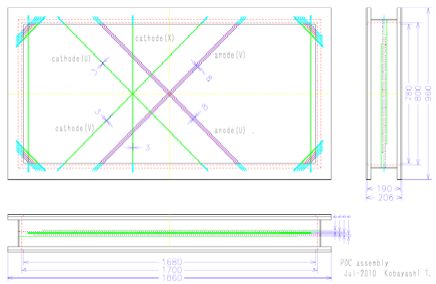
Fig 6 : PDC assembly
*Readout
(status)
¹@¹@¹@ We have tested the charge division readout
for cathode signals in order to reduce the readout channel.¹@ Cathode strips are daisy-chained by
resistors, and cathode charges are read out via charge sensitive pre amp in
every 8 strips.¹@ Using a prototype
detector (600mm x 480mm effective area) with roughly the same geometry,
position resolution of 1mm (rms) were obtained for x-rays.¹@ With this method, about 110ch of charge
sensitive preamp, shaping amp, and peak sensitive ADC¹fs are necessary to read 2
PDC¹fs.
¹@¹@¹@¹@ Since 2 proton events can not be handled
properly by this method, we are developing a new readout circuit: every cathode
signals are connected to charge sensitive preamp, shaper, sample & hold,
and digitized in the front-end board (FEB, 16ch/board), and digital data are
sent to the VME memory.¹@¹@ This method
also improve the position resolution by ~factor of 5.¹@ About 810 ch of circuits¹@
(8-9 FEB¹fs/plane x 6 planes) are necessary.
[7]¹@ Ion Chamber for Beam
(ICB)
*
Design
¹@¹@¹@ ICB is a multi-layer ion chamber, and
placed upstream of the target.¹@ It is
used to measure the charge of¹@ incident
secondary beams.
|
electrodes |
12É m-thick Al-Mylar , 10
anode & 11 cathode planes |
|
Anode-cathode
gap |
21mm |
|
window |
16É m-thick Aramid |
|
effective
area |
140mm
x 140mm x 420mm (deep) |
|
gas |
P10
@1atm |
|
HV |
anode(+) |
|
readout |
10ch,
preamp ( Mesytec-MPR16 with 10É s decay time), shaping amp (MSCF-16LE, active
BLR, unipolar output, 0.25É s
shaping time), & peak sensitive ADC (MADC32) |
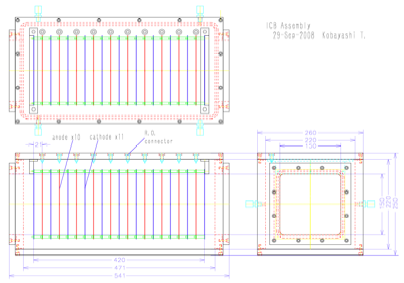
Fig 7 : ICB assembly
¹@[8]¹@ Ion
Chamber for Fragment¹@
(ICF)
*
Design
¹@¹@¹@ ICF is a multi layer ion chamber, and
placed after the SAMURAI magnet.¹@ It is
used to measure the charge of projectile fragments.
¹@¹@¹@ Due to several technical difficulties
(available size of double-sides Al-Mylar foils, method to make double-sided
segmented anodes, etc.), effective area of the present ICF is much smaller than
that of FDC2.¹@ We should have used the
wire cathode as well to have larger¹@
effective area.
|
electrodes |
12
anode & 13 cathode planes |
|
anode-cathode
gap |
20mm |
|
effective
area |
750mm
(H) x 400mm (V) x 480mm (deep) |
|
anode |
80É mÉ”Au-Al, 5mm pitch, 18
wires are or-ed to make a 90mm-wide strip, 2
strips are or-ed for readout (4ch/plane) |
|
cathode,
window |
12É m-thick Al-Mylar |
|
Gas |
P10
@1atm |
|
HV |
cathode
(-), anode is at ground potential |
|
readout |
4ch/plane
x 12 planes = 48ch, preamp ( Mesytec-MPR16 x3 with 10É s decay time), shaping
amp (MSCF-16LE x3, active BLR, unipolar output, 0.25É s shaping time), &
peak sensitive ADC (MADC32 x2) |
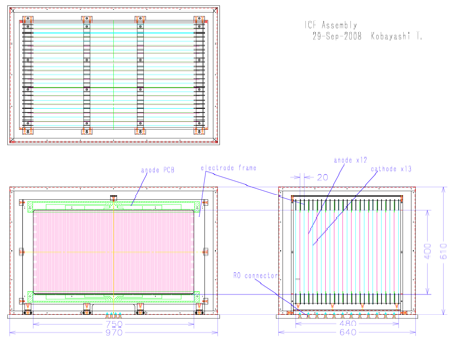
Fig 8 : ICF assembly
[9]¹@ Hodoscope for Fragment/Proton
(HODF, HODP)
*
Design
¹@¹@¹@ HODF and HODP are conventional
scintillator hodoscopes.¹@ They are
placed after FDC2 and ICF to measure TOF and charge of particles.
|
plastic
scintillator |
BC408,
1200mm(V) x 100mm(H) x 10mm(T) |
|
slat |
Plastic
is coupled to HPK H7195 PMT (with a booster connector) via 100mm-long
fishtail light guide. |
|
Effective
area |
16
slats/hodoscope, 1600mm(H) x 1200mm(V) |
|
HV |
32ch/hodoscope
x 2 = 64ch, with additional HV¹fs for booster, CAEN
A1733N x6(+4) |
|
Readout |
16ch
CAMAC discriminator (Phillips 7106) x4, 500nsec
logic & analog cable delay x 64, CAEN
32ch ADC V792AC x2 CAEN
32ch TDC V775AC x2 |
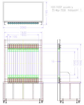
Fig 9 : HODF/HODP
Assembly
[10]¹@ Total Internal Reflection
Cherenkov (TIRC)
*
Design
¹@¹@¹@ TIRC is a Cherenkov detector operated at
the total internal reflection (TIR) threshold.¹@
Since photon numbers increase sharply at the TIR threshold, good
velocity resolution is expected.¹@¹@
Refractive index of the radiator chosen is n~1.9 so that the TIR
threshold is around 250 MeV/A.
|
radiator |
TAFD30(n~1.92),¹@ 65mm x 240mm x 2mmt¹@ (max. size available) |
|
PMT |
HPK
H6559 (3¹hÉ”) with
booster connector, radiator is viewed by 2 PMT¹fs.¹@ 10 PMT¹fs available |
|
effective
area |
632(317)mm
x 240mm(V), covered by 10(5) elements |
|
HV |
20(10)
ch,¹@ CAEN A1733N x2(1) |
|
readout |
20(10)
x 500nsec cable delay, CAEN 32ch ADC V792AC x1 |
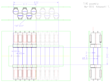
Fig 10 : TIRC assembly
[11]
Total Energy Detector (TED)
*
Design
|
crystal |
Pure
CsI, 100mm x 100mm x 50mm-thick |
|
PMT |
HPK
– R6233HA(3¹hÉ”),¹@¹@¹@ with non-UV window,¹@ booster connector |
|
breeder |
tapered,
with high breeder current (3mA @1kV),¹@
|
|
effective
area |
800mm(H)
x 400mm(V), with 8 x 4 (32) crystals |
|
HV |
32
ch,¹@ CAEN A1733N x3 |
|
readout |
32
x 500nsec cable delay, CAEN 32ch ADC V792AC x1 |
*
R&D for TED
¹@¹@¹@ As a total energy detector, we have
tested¹@ (1) NaI(Tl) coupled to PMT, (2)
HP-Ge crystal, (3) CsI(Tl) coupled to photodiode, using Ar & Kr &
secondary beams between 200 – 400 MeV/A.¹@
Energy resolution of 0.3 – 0.4 % (rms)¹@ for total energy of 25 – 30 GeV was obtained only at low
counting rate (below 1kHz).¹@
¹@¹@¹@ Since above detectors are relatively slow,
we have also tested pure CsI crystal coupled to PMT.¹@ It has smaller light output compared to CsI(Tl), but has faster
decay time and believed to be strong against the radiation damage.¹@ After high-current tapered breeder was
designed, energy resolution of 0.2 to 0.4% was observed for Kr beams at 400
MeV/A.¹@ By comparing the light output
between Ar and Kr beams, large saturation effect was observed.¹@ Since energy resolution between PMT with UV
window and with non-UV window has no noticeable difference, PMT with non-UV window
was selected.¹@ Light output was stable
for beam rates up to 10-20kHz.¹@ It was
also observed that the pulse shape for heavy ion is different from those for ÉΝ-rays, electrons, and
possibly protons.
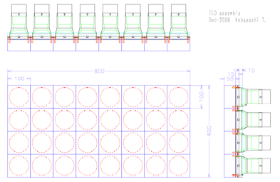
Fig 14 : TED assembly
Kobayash
@lambda.phys.tohoku.ac.jp
Updated
2-Sep-2011